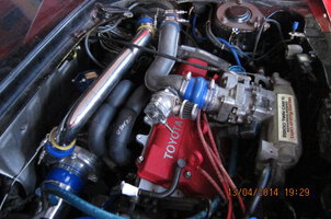
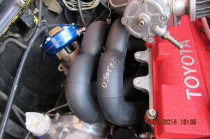
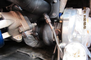
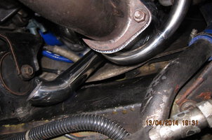
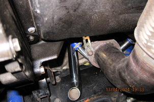
Also got my header ceramic coated and installed. A lot of piping work when replacing the former header to this one which involves a lot of modification of pipe and numerous trial & error of fitting problem when doing this on my own at home without any welding facilities. Have to do piece by piece and visit the welding shop numerous time as the car is stranded at home on stands. A lot time and effort put in. Car is in running condition now after been sleeping for a long time.

My MR2 turbo upgrade project
- Thread starter Green06
- Start date
- Replies 98
- Views 22K
-
See what others are reading now! Try Forums > Current Activity


Similar threads
The Marketplace Latest
-

Chrome delete
- Started by jeff6126
- Exterior and Body
Posts refresh every 5 minutes
Recent Posts
-

Tire Price list Zth
- Started by xbalance2002
- Wheel And Tyre
Search
Enjoying Zerotohundred?
Log-in for an ad-less experience