My MR2 turbo upgrade project

A6ttached are the photos that were not able to be posted last night.......
Photo # 3, 4 & 5..........finally.....
 
Rear Arm modification...........installed 10mm thk RCA plate and added 3mm washer as it was not thick enough for my setup. The principles is the same as for the front Arms. When lowering the car the geometry is out and this cause the lower arms to point upward. When negotiating a sharp corner, the car tend to roll and the wheel tend to move upward and this causes the arm to move upward which pulls in the wheel. Causing a positive camber. In the photo there is also the toe in link end being modified. In an unmodified situation this link will also point upward. So in sharp corner the toe link tends to pull in the wheel too causing a toe out of the wheel. So by modifying the toe link and get it to point downward will cause the wheel to toe in in sharp corners. I have personally conducted this setup to test and it is really scary and unable to drive fast in corners as the cars tends to snap out its tail. So with the modification the car can take corners safely with the car lowered.
Photo # 1 shows the installed RCA
Photo # 2 & 3 show both the left & right side arms and toe link
Photo #4 shows the modification done on the toe link end
 

Attachments

  • Rear RCA.jpg
    Rear RCA.jpg
    52.6 KB · Views: 250
  • Rear arm (left ) with RCA.jpg
    Rear arm (left ) with RCA.jpg
    57.7 KB · Views: 240
  • Rear arm (right ) with RCA.jpg
    Rear arm (right ) with RCA.jpg
    63.5 KB · Views: 251
  • Rear Toe link mod & RCA.jpg
    Rear Toe link mod & RCA.jpg
    58.4 KB · Views: 262
problem with this forum, photos keep missing................no Good !

Next project ...fabricating 245 TB mounting flanges and fuel rail bar for Bosch top feed injectors.
Follow on would be welding the 245 TB mounting flange to a modified Intake manifold. There will be some work to be done on the Intake manifold as it has a 225 TB mounting flange on.

In store project will be modifying 2 TRUST intercoolers, combining it to make one big unit.

Stay tune...............:biggrin: :driver:
 

Attachments

  • Mounting plate cut out.jpg
    Mounting plate cut out.jpg
    49.7 KB · Views: 232
  • Blank fuel bar ID 13 m or 0.5 inch.jpg
    Blank fuel bar ID 13 m or 0.5 inch.jpg
    51.9 KB · Views: 235
  • Blank fuel bar marked up.jpg
    Blank fuel bar marked up.jpg
    47.2 KB · Views: 232
  • TRUST Intercoolers.jpg
    TRUST Intercoolers.jpg
    71.1 KB · Views: 248
Next, tackle the toe in problem when lowering the MR2. MR2 has a unique setup with the steering rack installed in front of the front wheel where else all other cars ( Evo, RX, STI, Protons, and others daily vehicles ) have their steering rack installed behind the front wheel. ( I believe the designer did it with a purpose ie. to make it oversteer.) When the car is lowered, both left & right side steering rack end points upwards. During a sharp corner. The wheel moves upward further thus causing the steering link to moves up and this pulls in the wheel and indirectly causing excessive toe in. This makes the car oversteer more and it is dangerous, ( I have experienced this B4 I write this as I have been doing some practical research on it.) Extremely dangerous in corners and you can't go fast, the tails keep wanna swing out. The solution is to install a pair of this aftermarket link end.
See attached photo #1.......This helps to bring down the link to almost parallel to the road or neutral position. So during a sharp corners, the link will not pull in too much that causes excessive toe in.

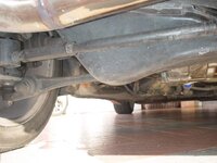
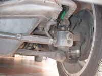
The #2 & 3 photo shows the arm with the RCA and the steering link end ( without the aftermarket link end ) pointing upward.....while the lower arms stay at neutral or parallel to the ground.

The #4 & 5 photo shows the the aftermarket link end installed and notice the it is parallel / neutral to the ground.


This is the set up i am looking for. Bro, might to tell where you bought the aftermarket front rack end link?

As for the rear toe bar, do u weld a new bracket to the adjustable rod? or just patch a steel plate to it?

Very nice update on your upgrade. thanks for sharing.
 
I got my end link from RHD Japan. ( rhdjapan.com ). If you are going to install them, get a pair of RCA too. ( Ask Alvin {TOMs}, he might have it ).The RCA makes your lower arm pointing downward or parallel to the ground if you lowered to an extend. At any time NEVER allow the lower arm to point upward as it makes your camber positive. DO NOT forget to replace the steering end rack to a longer one because the ori one is just too short - not enough of thread into the link end - DANGEROUS!
As for the rear toe link,a new piece was fabricated and welded to the threaded link end.
Hope you will enjoy a new found experience on yr MR2 handling..............:driver:
 
Yeah. I installed the RCA. It really give much better handling. I also duplicated few set too. hehe... Please contact me if anyone interested.

:rofl:
 
Joyride, did you check your steering end rack? How many threads was into the end link? Need to watch out. You probably having 3 to 4 threads screwed in only and thats is not enough!! :listen:

---------- Post added at 10:46 PM ---------- Previous post was at 10:43 PM ----------

Joyride, since you added RCA to your front, did you have it for your rear? Consider have it installed. I wud suggest 13 mm thk. If you fabricate them, I might want a pair. Tq.:driver:
 
Back again with some updates after some weeks of silence, actually getting stuff fabricated etc.
Attached are the photos #1 of the 245 TB mounting plates.
Photo# 2 is the fuel bar drilled for Bosch injectors.
 

Attachments

  • 245 TB mounting plates.jpg
    245 TB mounting plates.jpg
    58.1 KB · Views: 213
Had to do minimal posting as the system unable to take much photos at one time............
Here is the IC with end tank cut out. Intent to combine ( marry ) 2 IC into one.
 

Attachments

  • IC with cut out end tanjs.jpg
    IC with cut out end tanjs.jpg
    70.9 KB · Views: 235
  • IC without end tanks.jpg
    IC without end tanks.jpg
    75.2 KB · Views: 224
  • IC to be combined.jpg
    IC to be combined.jpg
    94.2 KB · Views: 223
Also did some upgrade on my MegaSquirt DIY ECU project............
Photo # 1 injector driver board that takes either high or low impedance injectors without need for resistor pack.
Photo # 2 & 3 show the output pin adapter. This adapter will handle much higher current than the MS original one. Photo # 2 also show an attachement for the ignition module ( together with the output pin board ). The ignition module will fire 2 Twin coil pack which will be a wasted spark setup. The triggering will be a 60-2 crank mounted system. Photo will be later. The triggering wheel have been installed sometime ago when rebuilding the engine. VR sensor have yet to be installed.
Photo # 4 show the complete MS ECU internal.
Photo # 5 show the 4 bar MAP sensor with barometric correction.
ECU is ready, wiring harness yet to be completed. Still a long way to get the ECU installed as the other parts needs to be fabricated and installed. ECU will be the last to go in.
 

Attachments

  • MS1 Injector driver.jpg
    MS1 Injector driver.jpg
    72.3 KB · Views: 283
  • MS1 & adapter attachment.jpg
    MS1 & adapter attachment.jpg
    89.9 KB · Views: 226
  • MS1 with output pin attached.jpg
    MS1 with output pin attached.jpg
    75.8 KB · Views: 242
  • MS1 with adapter attachement.jpg
    MS1 with adapter attachement.jpg
    86.1 KB · Views: 229
  • MS1 with 4 bar MAP sensor and barometric correction.jpg
    MS1 with 4 bar MAP sensor and barometric correction.jpg
    61.1 KB · Views: 268
Did modification to the intake manifold that will have a 245 TB later........
Photo # 1 is the 245 TB which will receive some modification later
Photo # 2 & 3 Modified intake manifold with 225 TB mounting plate cut out.
Photo # 4 Modified intake manifold patched to receive 245TB later.
Photo # 5 245 TB mounting to be attached to the intake manifold later.
 

Attachments

  • 245 TB.jpg
    245 TB.jpg
    49.7 KB · Views: 234
  • Intake manifold with 225 TB mounting cut out..jpg
    Intake manifold with 225 TB mounting cut out..jpg
    62.3 KB · Views: 273
  • Intake manifold with 225 TB mounting cut out top view..jpg
    Intake manifold with 225 TB mounting cut out top view..jpg
    61.9 KB · Views: 261
  • Intake manifold patched..jpg
    Intake manifold patched..jpg
    61.1 KB · Views: 257
  • 245 TB mounting plates to be attached.jpg
    245 TB mounting plates to be attached.jpg
    48 KB · Views: 235
Made some progress...............
Photo #1 245 TB mounting plate welded onto the intake manifold with IAT bung welded in the air stream and IAC air passage cut.
Photo #2 245 TB mounted to check for clearance etc.
Need to polish up the intake manifold and TB.............later.............
 

Attachments

  • 245 TB mounting plate with IAT bung and air groove for IAC..jpg
    245 TB mounting plate with IAT bung and air groove for IAC..jpg
    70.2 KB · Views: 242
  • Intake manifold with 245 TB mounted temporary..jpg
    Intake manifold with 245 TB mounted temporary..jpg
    69.1 KB · Views: 301
How is this mega project progress so far? hope you can ge the car out and run in before CNY.
 
this uncle lagi terror than the younger mr owner here.....hahahaha.....
 
Hi, modified my 245 TB.............
photo #1 the ori 245 TB plate bar
photo #2 modified the plate bar so that there is less obstruction to airflow
photo #3 front view of my moded 245 TB and polished internals
photo #4 see the reduced airway......less obstruction to the air flow
 

Attachments

  • 245 TB plate bar.jpg
    245 TB plate bar.jpg
    58.8 KB · Views: 219
  • 245 TB plate bar modified.jpg
    245 TB plate bar modified.jpg
    64.6 KB · Views: 234
  • 245 TB front view with modified plate bar.jpg
    245 TB front view with modified plate bar.jpg
    56.8 KB · Views: 248
  • 245 TB plate bar modified -1.jpg
    245 TB plate bar modified -1.jpg
    42.7 KB · Views: 267
Back again with a few project completed and some in progress.
Photo#1 245 TB with Custom Air Intake header installed and being running for sometime.
Photo#2 Replaced my Ti titanium muffler with this straight thru....cheap skate one lah a direct copy from Apexi I beleieve. 50% louder than the Ti but a lot more responsive in revving up & turbo spool up.
 

Attachments

  • 3 inch straight thru Exh muffler.JPG
    3 inch straight thru Exh muffler.JPG
    99.9 KB · Views: 252

Similar threads

Posts refresh every 5 minutes


Search

Online now

Enjoying Zerotohundred?

Log-in for an ad-less experience