DIY LED brake lights. Need help.

shiroitenshi

3,000 RPM
Senior Member
Apr 18, 2006
3,676
170
1,663
rs online or element14.com

both got branch in malaysia if you want luxeon leds and drivers

Sent from my GT-I9100G using Tapatalk 2

---------- Post added at 01:19 AM ---------- 6 hour anti-bump limit - Previous post was at 01:14 AM ----------

It is not a good idea to drive the LED using this method. A proper way should be controlling the current but not the voltage. Reason why is because LED has a very steep V-I curve. A slight changes in voltages will cause a huge changes in current. If the LED has a low side in forward voltage due to manufacturing batch, then it may end up blowing these LED in a short period of time.
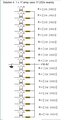
isn't the lm7809 current limited to 1A? Why would it be a problem?

Sent from my GT-I9100G using Tapatalk 2


oh, nvm, i get your point, but easily solvable by not running the leds in series right?, so LM7805/LM7809 + resistors + leds in parallel is workable?

btw stpcar, I used the lm7809 + caps for the smarttag, not LEDs.
 
Last edited:

artful

Junior Member
Senior Member
Aug 29, 2007
20
0
1,501
Hi all sifu,

If i need brake light function with my below setting, what type of diode and extra resistor to add??

HPWS-FH00-H4000 Lumileds Superflux LED
Vf : 2.6V(typ)
If : 70mA(max)
Total LED: 17

turning it on with a resistor in the 12V car (maximum voltage 14.4V) about 50mA.
I'm using 【1W 240Ω】 resistor for each superflux LED. Below is the diagram
 

Attachments

goohtj

Known Member
Senior Member
Dec 27, 2004
57
12
5,008
Hi all sifu,

If i need brake light function with my below setting, what type of diode and extra resistor to add??

HPWS-FH00-H4000 Lumileds Superflux LED
Vf : 2.6V(typ)
If : 70mA(max)
Total LED: 17

turning it on with a resistor in the 12V car (maximum voltage 14.4V) about 50mA.
I'm using 【1W 240Ω】 resistor for each superflux LED. Below is the diagram
your is a single led per bank - alot of power loss

why not connect 5 leds in serie per bank
5 x 2.6v = 13v
could add 28ohm resistor ( 14.4v-13v =1.4v / 50ma = 28ohm)

note: this brings up to 15 leds or 20 leds ..
 

levin818

1,000 RPM
Senior Member
Nov 29, 2003
1,260
321
3,183
Shah Alam
Visit site
... so LM7805/LM7809 + resistors + leds in parallel is workable?...
Yes connection in this way is better! The LED brightness will not affected by the variation of battery voltage. But the max output current is limited by the type of Voltage Regulator being use.

---------- Post added at 11:57 PM ---------- 6 hour anti-bump limit - Previous post was at 11:53 PM ----------

I personally find this this page is quite informative. It has a simple resistor current control circuit to a more complicated MOSFET constant current driver. Great for those who want to DIY.
http://www.pcbheaven.com/userpages/LED_driving_and_controlling_methods/

---------- Post added 08-12-2013 at 12:00 AM ---------- 6 hour anti-bump limit - Previous post was 08-11-2013 at 11:57 PM ----------

Can someone help me to sort my led brake light issue? I see some experts around here would really appreciate if someone could sort it out.
Is it from 8-series :O
Yes it can be recover. But the plastic cover might need to cut open in order to reach the LEDs inside.
 
Last edited:

stupidcar

5,000 RPM
Thread starter
Mar 18, 2013
5,567
850
713
Kuala Lumpur
Hi all sifu,

If i need brake light function with my below setting, what type of diode and extra resistor to add??

HPWS-FH00-H4000 Lumileds Superflux LED
Vf : 2.6V(typ)
If : 70mA(max)
Total LED: 17

turning it on with a resistor in the 12V car (maximum voltage 14.4V) about 50mA.
I'm using 【1W 240Ω】 resistor for each superflux LED. Below is the diagram
Make it in series is way better. The led wizard should have a few options to choose right?

Can someone help me to sort my led brake light issue? I see some experts around here would really appreciate if someone could sort it out.
Should be an easy fix.
Use positive point screw and just unscrew it.
U should see what are they. If you are lucky, maybe it's just bulbs.
Bulbs are very easy to replace.
 

levin818

1,000 RPM
Senior Member
Nov 29, 2003
1,260
321
3,183
Shah Alam
Visit site
Hi all sifu,

If i need brake light function with my below setting, what type of diode and extra resistor to add??

HPWS-FH00-H4000 Lumileds Superflux LED
Vf : 2.6V(typ)
If : 70mA(max)
Total LED: 17

turning it on with a resistor in the 12V car (maximum voltage 14.4V) about 50mA.
I'm using 【1W 240Ω】 resistor for each superflux LED. Below is the diagram
Wow... you have a great LED. Where did you get it from?
HPWS-FH00 can actually withstand 150mA and produce 11 lm flux.
If you drive it at 70mA, it only produce about 7 lm of flux.
However, to drive it at 150mA, you need to attach a proper heat sink on the PCB to dissipate the large amount of heat generated. Otherwise the LED will be dying young.

[Characteristic]
Vf = 2.19V~3.15V (Typ. 2.8V)
If = 150mA
Total Flux = 11 lm @ 150mA

Suggest you connect 4 LED in series + 22ohm (1W) resistor
At V batt = 14.4V, Vf = 2.8V, I = 145mA
At V batt = 12.5V, Vf = 2.58V, I = 99mA

Or if connected 3 LED in series + 43ohm (1W) resistor
At V batt = 14.4V, Vf = 2.8V, I = 140mA
At V batt = 12.5V, Vf = 2.6V, I = 109mA

Unless you want to apply a constant current driver, otherwise the brightness will vary with the changes of battery voltage level.
 

artful

Junior Member
Senior Member
Aug 29, 2007
20
0
1,501
your is a single led per bank - alot of power loss

why not connect 5 leds in serie per bank
5 x 2.6v = 13v
could add 28ohm resistor ( 14.4v-13v =1.4v / 50ma = 28ohm)

note: this brings up to 15 leds or 20 leds ..
Hi goohtj,
Ohhh cuz me no knowledge about electrical stuff. This setup also given by the supplier.
So what will happen alot of power loss for this setup? Longevity of the LED ok with this setup??

Make it in series is way better. The led wizard should have a few options to choose right?
Hi stupidcar,
I would like too, but i'm not using any PCB board for this setup. I'm using T10 PCB with each superflux LED. I scare later wire is mess up. Hahahaaa...see below image for the T10 PCB

Wow... you have a great LED. Where did you get it from?
HPWS-FH00 can actually withstand 150mA and produce 11 lm flux.
If you drive it at 70mA, it only produce about 7 lm of flux.
However, to drive it at 150mA, you need to attach a proper heat sink on the PCB to dissipate the large amount of heat generated. Otherwise the LED will be dying young.

[Characteristic]
Vf = 2.19V~3.15V (Typ. 2.8V)
If = 150mA
Total Flux = 11 lm @ 150mA

Suggest you connect 4 LED in series + 22ohm (1W) resistor
At V batt = 14.4V, Vf = 2.8V, I = 145mA
At V batt = 12.5V, Vf = 2.58V, I = 99mA

Or if connected 3 LED in series + 43ohm (1W) resistor
At V batt = 14.4V, Vf = 2.8V, I = 140mA
At V batt = 12.5V, Vf = 2.6V, I = 109mA

Unless you want to apply a constant current driver, otherwise the brightness will vary with the changes of battery voltage level.
Hi levin818,
Sorry i wrongly given the product code. the correct Lumileds superflux led is
HPWT-RH02 RedOrange
Vf : 2.6V(typ)
If : 70mA(max)
Flux: (6.0-9.7lm)

I bought it while i was in Japan trip. LUMILEDS > SuperFlux - SuperFlux HPWT-RH02 RedOrange - LED
Why i don't want to go for series 4 or 3 LED because i'm not using any PCB board, I'm using T10Flux PCB for each superflux LED. (see image). I still can go for series 4 LED setup but max my tail lamp only got 17hole.(see image) 4LED x 4bank = 16Led balance 1LED how??

PS. To all sifu, sorry to mention i got no knowledge for electrical stuff. Hope all sifu can guide me hehe. Thanks
 

Attachments

stupidcar

5,000 RPM
Thread starter
Mar 18, 2013
5,567
850
713
Kuala Lumpur
Hi goohtj,
Ohhh cuz me no knowledge about electrical stuff. This setup also given by the supplier.
So what will happen alot of power loss for this setup? Longevity of the LED ok with this setup??


Hi stupidcar,
I would like too, but i'm not using any PCB board for this setup. I'm using T10 PCB with each superflux LED. I scare later wire is mess up. Hahahaaa...see below image for the T10 PCB


Hi levin818,
Sorry i wrongly given the product code. the correct Lumileds superflux led is
HPWT-RH02 RedOrange
Vf : 2.6V(typ)
If : 70mA(max)
Flux: (6.0-9.7lm)

I bought it while i was in Japan trip. LUMILEDS > SuperFlux - SuperFlux HPWT-RH02 RedOrange - LED
Why i don't want to go for series 4 or 3 LED because i'm not using any PCB board, I'm using T10Flux PCB for each superflux LED. (see image). I still can go for series 4 LED setup but max my tail lamp only got 17hole.(see image) 4LED x 4bank = 16Led balance 1LED how??

PS. To all sifu, sorry to mention i got no knowledge for electrical stuff. Hope all sifu can guide me hehe. Thanks
Odd number kinda messy weh. How about u do 4x4 then let the last one solo?
But actually, I'm not sure what im talking about ahha.
You all too high tech dy. Im gonna let the other guys comment la.
 

thilak79

Known Member
Senior Member
Jan 29, 2004
122
2
3,018
Make it in series is way better. The led wizard should have a few options to choose right?


Should be an easy fix.
Use positive point screw and just unscrew it.
U should see what are they. If you are lucky, maybe it's just bulbs.
Bulbs are very easy to replace.
Thanks. That's the problem. I don't have the confident on doing the electronics stuff. Never had. :( anyone? :confused:
 

goohtj

Known Member
Senior Member
Dec 27, 2004
57
12
5,008
Artful, function of replacing to led is to save energy.
normal bulb = 10 ~20watts
your 17banks led = 0.72watts x 17 = 12.24watts

as other sifu said, 4 x 4 bank + 1 ( yours) will do =17 leds
( 5 banks x 0.72w = 3.6watts)
parts needed = 4 x 80ohm 1/2watt resistor
1 x 240ohm 1 watt resistor

happy DIY ing..
 

artful

Junior Member
Senior Member
Aug 29, 2007
20
0
1,501
Odd number kinda messy weh. How about u do 4x4 then let the last one solo?
But actually, I'm not sure what im talking about ahha.
You all too high tech dy. Im gonna let the other guys comment la.
Haha i think i'll do 4x4 then.

Artful, function of replacing to led is to save energy.
normal bulb = 10 ~20watts
your 17banks led = 0.72watts x 17 = 12.24watts

as other sifu said, 4 x 4 bank + 1 ( yours) will do =17 leds
( 5 banks x 0.72w = 3.6watts)
parts needed = 4 x 80ohm 1/2watt resistor
1 x 240ohm 1 watt resistor

happy DIY ing..
goohtj,
Hahaha sorry forgot to tell you that i'm not replacing to led, i'm adding new LED to my tail light. Original tail light is using LED.

Than if i go for 3 x 6bank = 18 LED, what part should i need?? and how about the brake light function??
 

goohtj

Known Member
Senior Member
Dec 27, 2004
57
12
5,008
Haha i think i'll do 4x4 then.


goohtj,
Hahaha sorry forgot to tell you that i'm not replacing to led, i'm adding new LED to my tail light. Original tail light is using LED.

Than if i go for 3 x 6bank = 18 LED, what part should i need?? and how about the brake light function??
so, just hide 1 led...
you need 6 resistors 1/2watt 132ohms (base on 14.4v @50ma)(12.6v @36ma)
min 100ohms ~ 132ohm max - safe zone value

in using 100ohm resistor ( 14.4v @ 66ma)(12.6v @ 48ma) - brighter

you are advice to check your leds for equal brightness before installing.
 

levin818

1,000 RPM
Senior Member
Nov 29, 2003
1,260
321
3,183
Shah Alam
Visit site
Hi levin818,
Sorry i wrongly given the product code. the correct Lumileds superflux led is
HPWT-RH02 RedOrange
Vf : 2.6V(typ)
If : 70mA(max)
Flux: (6.0-9.7lm)

I bought it while i was in Japan trip. LUMILEDS > SuperFlux - SuperFlux HPWT-RH02 RedOrange - LED
Why i don't want to go for series 4 or 3 LED because i'm not using any PCB board, I'm using T10Flux PCB for each superflux LED. (see image). I still can go for series 4 LED setup but max my tail lamp only got 17hole.(see image) 4LED x 4bank = 16Led balance 1LED how??

PS. To all sifu, sorry to mention i got no knowledge for electrical stuff. Hope all sifu can guide me hehe. Thanks
You have a good LED. Yes you can light up 17 LEDs in equal brightness but you need a constant current driver. Alternatively, you may use Voltage Regulator IC 7809 to clamp the voltage at 9v before supply it to the LED (as suggested by Shiro). It will have very close result with using constant current driver.

---------- Post added at 03:46 AM ---------- 6 hour anti-bump limit - Previous post was at 01:24 AM ----------

Since your LED didn't attach to any heat sink, it is advice not to drive it beyond 50mA (from the datasheet)
Lets fix tail light current at 30mA, brake light current at 50mA. You may reduce the current if you see that its too bright.

From your LED's V-I curve:
When I = 50mA, Vf = 2.45V
When I = 30mA, Vf = 2.26V

[Brake Light] (+) -- 7809 -- diode ---------┐
[Tail Light] ...(+) -- 7809 -- diode -- 6R2 --•-- 22R -- LED -- LED -- LED ---•-- (-)
............................................................└-- 22R -- LED -- LED -- LED --┘

[Brake Light] (+) -- 7809 -- diode ---------┐
[Tail Light] ...(+) -- 7809 -- diode -- 56R --•-- 75R ---------- LED -- LED ----- (-)

Diode = 1N4007, all resistor @ 1/4W 1% tolerance
 
Last edited:

Random Post Every 5 Minutes

Hi all,

Please help me decide between 2009 Mercedes c200k and Lexus IS250. Both unreg, recon.

Mercedes has more brand power in Malaysia ( people think its more prestigious)
Road tax is cheaper
Better fuel consumption
Relatively better resale value
Low reliability for a4 yrs old car
Bland interior


Lexus
More reliable
Smooth V6
High fuel consumption
Excellent interior
Great features
Reliability

Price is almost the same and rear leg room isnt a big issue for me...
Ask a question, start a discussion or post something for sale!
Post thread

Online now

Enjoying Zerotohundred?

Log-in for an ad-less experience