O2 wiring... need help?

r60262

Known Member
Senior Member
Joined
Mar 23, 2006
Messages
282
Points
1,516
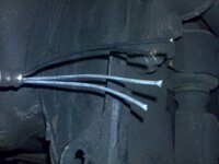
anyone can help me to find this O2 sensor wiring for svt? got 4 wire. black,black with line red, red with line black n pink. this wire to system. for O2 sensor got 4 wire. 2 black n 2 white.... or other method to check this sensor.... urgent... now i don't use this sensor... machine running fine. oil consuption also ok. but i need to clear error code 21. thanks

---------- Post added at 03:29 AM ---------- 6 hour anti-bump limit - Previous post was at 03:28 AM ----------


URL]
 

Attachments

  • 20091125410.jpg
    20091125410.jpg
    36.9 KB · Views: 174
O2 warming - 12v
O2 warming - Grounded
O2 signal positive: Pin 23
O2 signal ground: Grounded

mostly it will be like this...
which is which...can't really tell...

perhaps... you might need to refer to this pinout :

http://i229.photobucket.com/albums/ee18/4age20v/ECU_AE101_20V_4A-GE-Manual_01.jpg

only got 2 wire...located at these pins :

M6 (blk) - Oxygen sensor
N14 (Pink-Blk) - Heated Oxygen sensor
 
Last edited:
tq bro for ur help. now i know signal wire... i'll try myself... thanks again....
 
Rais, you are running an auto ECU 89661-1A180. It has slightly difference in pin out with M/T's.

SVT's O2 sensor has 4 wires. As Chinozie said, 2 is heating element (HT) and another will supply signal to ECU (O2). You can easily identify it on the system hardness by tracing it to the ECU terminals, but on the O2 side, you need to find out which one is which from the other car.

HT - N connector pin 8
HT - Battery (+)
O2 - M connector pin 6
O2 - M connector pin 13

HT is connected to a non polarity heating element, so either way's connection will have no problem.
But for O2, one is getting bias voltage from the ECU, another one is signal output to the ECU. This 2 must be connected correctly.
 
Last edited:
and please don't forget about how to handle O2 sensors...!!!

• DO NOT drop or use an oxygen sensor that has been dropped as this may have caused shock damage to the ceramic element
• DO NOT use any compounds on or around the sensor unless labeled as oxygen sensor friendly products
• DO NOT use impact wrench or conventional socket type wrench to install sensor
• DO NOT allow sensor or lead wire to touch exhaust manifold or any other hot component
• DO NOT expose this product to water, oil, windshield cleaner, anti-corrosion oil, grease, terminal cleaner, etc.
• DO NOT use leaded fuels, silicone or metal based additives
• DO NOT store under high humidity conditions
• DO NOT apply voltage to the sensor !!!
 
thanks very much bro... jod done by myself. base on ur info la... my car auto.. just to share.. n guide me if i'm wrong..

m6 = black (screened wire) = signal o2
n14 = pink/black = heated o2 sensor( ground signal )
black stripe red = +12v (key on)
red stripe black = ground for sensor

for sensor 4 wire
white = signal o2 sensor
white = ground
black = heated o2 sensor
black = +12v (key on)

now error code 21 disappear.... as what u told me b4.. another prb solve.... thanks bro.
 

Attachments

  • 20 Valve Pins 1999.doc
    66.5 KB · Views: 245
Rais, i am afraid you have a wrong connection and your O2 may not working properly.

Pelase check my idea as follow:

white = black (screened wire) ==> Pin M6, "OX" (signal O2)
white = red stripe black ==> Pin M13, "OX+" (signal O2)
black = pink/black ==> Pin N8, "HT" (heater)
black = black stripe red ==> +12v (key on)
 
ok wong i'll check again. but i'm confuse here.. for heater as u said pin n8 not same la with my connector. i confirm that heater (pink/black) is pin N14 as chinozie said. also i already check continuity between wire. conform pink/black is n14. but i'll check again. thanks for info....
 
and please don't forget about how to handle O2 sensors...!!!

• DO NOT drop or use an oxygen sensor that has been dropped as this may have caused shock damage to the ceramic element
• DO NOT use any compounds on or around the sensor unless labeled as oxygen sensor friendly products
• DO NOT use impact wrench or conventional socket type wrench to install sensor
• DO NOT allow sensor or lead wire to touch exhaust manifold or any other hot component
• DO NOT expose this product to water, oil, windshield cleaner, anti-corrosion oil, grease, terminal cleaner, etc.
• DO NOT use leaded fuels, silicone or metal based additives
• DO NOT store under high humidity conditions
• DO NOT apply voltage to the sensor !!!

Hey sifu sifu sekalian, want to ask this. It's regarding O2 sensor handling.

Scenario is like this. haven't install yet.
Just got my Innovate LC1, it came with a Mitsu compatible O2 sensor. So this means, i can't plug and play this O2 with a stock one. i need to drill another hole or mod the current position.

Option 1 - Mod the current O2 sensor hole to accommodate this O2 sensor and remove the old one

Option 2 - Drill another hole to fit in this O2 sensor and leave the current sensor in (recommended by one sifu too)

So, option 2 were to leave the stock O2 sensor there, will it spoil? In the Innovate caution menu, power must start 1st b4 car start so the O2 is powerup and ready. If the power does not start for the sensor and the engine start 1st, it will spoil the sensor.

Is the stock O2 sensor has the same handling process? If yes, i rather remove it and keep it than to spoil it.
 
km_chew - you might need to refer to this pdf file...

lots of details inside...

http://www.innovatemotorsports.com/support/manual/LC-1_Manual.pdf

happy reading...
 
ok wong i'll check again. but i'm confuse here.. for heater as u said pin n8 not same la with my connector. i confirm that heater (pink/black) is pin N14 as chinozie said. also i already check continuity between wire. conform pink/black is n14. but i'll check again. thanks for info....

Chinozie's attachment is referring to M/T's wiring where "HT" located at N14. But your's is A/T, "HT" is located at N8. And according to your attachment, "HT" at both M/T and A/T has same colour code, Pink-Blk.
So, if you are running an ori A/T's wiring, you should have Pink-Blk at N8.
Could you confirm this?

For A/T wiring, N14 is referring to "E1", which is Engine Ground. If you connect your heater to this pin, you will get it heated up whenever you turn on your IG switch. I am worried that it might shorten the lifespand of the O2 sensor (?)
For standard setting, ECU will only pull "HT" to ground (turn on the heater) at cold start. After the O2 reach the working temperature, the ECU will disconnect "HT" from ground, and shut down the heater.
 
ook.... wong u right..... actually i use n8 for heater pink/black...

white = black (screened wire) ==> Pin M6, "OX" (signal O2)
white = red stripe black ==> Pin M13, "OX+" (signal O2)
black = pink/black ==> Pin N8, "HT" (heater)
black = black stripe red ==> +12v (key on)
thanks again all members.... prob solve..


Write your reply...

Similar threads

Posts refresh every 5 minutes


Search

Online now

Enjoying Zerotohundred?

Log-in for an ad-less experience